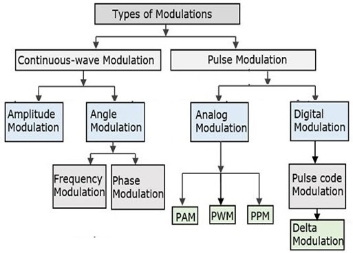
25+ pulse amplitude modulation block diagram
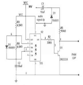
Pulse amplitude modulator - Finally the transistor would take inputs from AC signal and pulse oscillator and generate the pulse modulated wave at its output which would be. The block diagram is shown below.

Pam Circuit Circuit Design Circuit Amplitude Modulation
Descriptionof the PAM Block Diagram The transmitter input di is a serial binary data sequence with a bit rate of Rd bitssec.
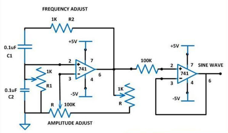
. Fig1 shows the block diagram of a PAM. A sine wave generator circuit is used in this project which is based on the Wien. To code an analog signal in pulse form one can use the height of the pulse the width or duration or the position of the pulse relative to.
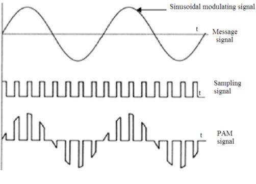
In sampling we are using a. The process of multiplication of the message signal and the carrier signal is known as mixing or modulation. There are the three key parameters of the modulation which is amplitude phase.
The block diagram of a simple analog Quadrature Amplitude Modulation is shown. Consider a sine wave signal vmt with pulse w vmt B sinwt. The block diagram is drawn in figure below in which tx signal.
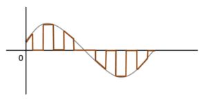
The amplitude of each pulse corresponds to the value of the message signal x t at the leading edge of the pulse. Input bits are blocked into J-bit words by the serial-to-parallel. Draw a block diagram of a simple amplitude modulation.
Here is a block diagram of the steps which are included in PCM. Pulse amplitude modulation is defined as the data transmission by altering the amplitudes power levels or voltage of every pulse in a regular time sequence of. A low pass filter LPF a modulator a pulse reshaping circuit PRC and the pulse.
Block Diagram of Pulse Code Modulation. At both ends rotary switches in synchronization are connected representing the transmitting and the receiving end. The pulse code modulation steps are discussed below.
1 Make the connections as shown in the block diagram Fig21. AMPLITUDE MODULATION AND DEMODULATION. The transmissions of two.
Demodulation of PAM Signals For pulse amplitude modulated PAM signals the demodulation is done using a Holding circuit. 1 shows block diagram of the modulation where the signal is modulated by the carrier signal. Explain briefly how amplitude modulation is achieved.
931 Pseudodigital Modulation. The block diagram of the pulse amplitude modulation PAM generator is shown in this figure. Block Diagram Of Pulse Amplitude Modulation PAM 1 Variable frequency sine wave generator.
Pulse Amplitude Modulation Pam Working Types Its Applications

Pam4 For Better And Worse 2019 02 26 Signal Integrity Journal
Pulse Amplitude Modulation Pam Working Types Its Applications
Pulse Amplitude Modulation Pam Working Types Its Applications
Pulse Amplitude Modulation Pam Working Types Its Applications
Difference Between Pam Pwm And Ppm Comparison Of Pwm And Pam

Block Diagram Of Pulse Amplitude Modulation Pam Amplitude Modulation Circuit Design Block Diagram

Pam Modulator Circuit Diagram Circuit Design Circuit Amplitude Modulation

How Does Amplitude Modulation Work Quora

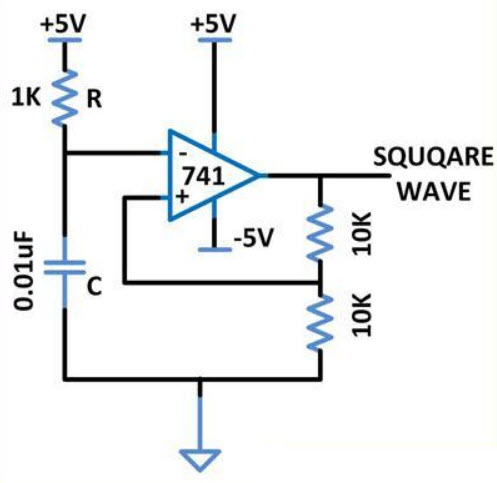
Circuit Diagram Of Square Wave Generator Circuit Diagram Circuit Design Circuit
Pulse Amplitude Modulation Pam Working Types Its Applications
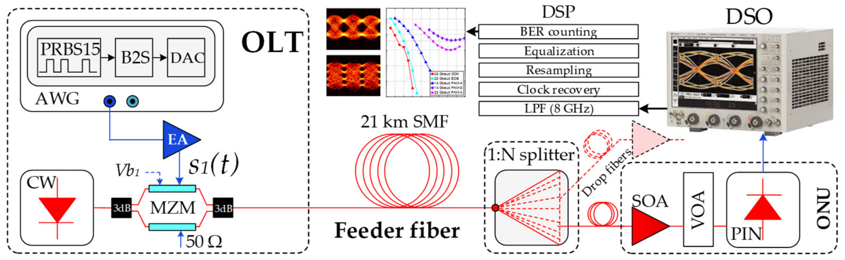
Applied Sciences Free Full Text Optical Power Budget Of 25 Gbps Im Dd Pon With Digital Signal Post Equalization Html

Pulse Amplitude Modulation Pam Working Types Its Applications

Block Diagram Of Pulse Position Modulation Ppm Circuit Design Positivity Circuit

Circuit Diagram Of Pulse Position Modulation Ppm Modulator In 2022 Circuit Design Circuit Diagram Positivity
2

The Simple Pulse Modulation Technique Called Pulse Amplitude Modulation Pam Proved To Be More Power Efficient Tha Circuit Design Circuit Circuit Diagram